Product overview
Select by pipe data, operating duty and installation condition
Universal pipe couplings join two plain-ended pipes without welding or flanging at the connection. They are used in new water pipelines, replacement sections, network rehabilitation and transitions between compatible pipe materials or outside diameters.
Conflex offers universal, restrained and pipe-specific coupling configurations for ductile iron, steel, PVC and PE applications. A steel pipe coupling and a PVC pipe coupling may require different OD bands, gasket details, support and restraint even when the nominal pipe sizes match.
The correct water pipe coupling depends on both measured outside diameters, pipe material, working pressure, medium, temperature, angular alignment and the need for restraint. Share data for both pipe ends whenever they differ.
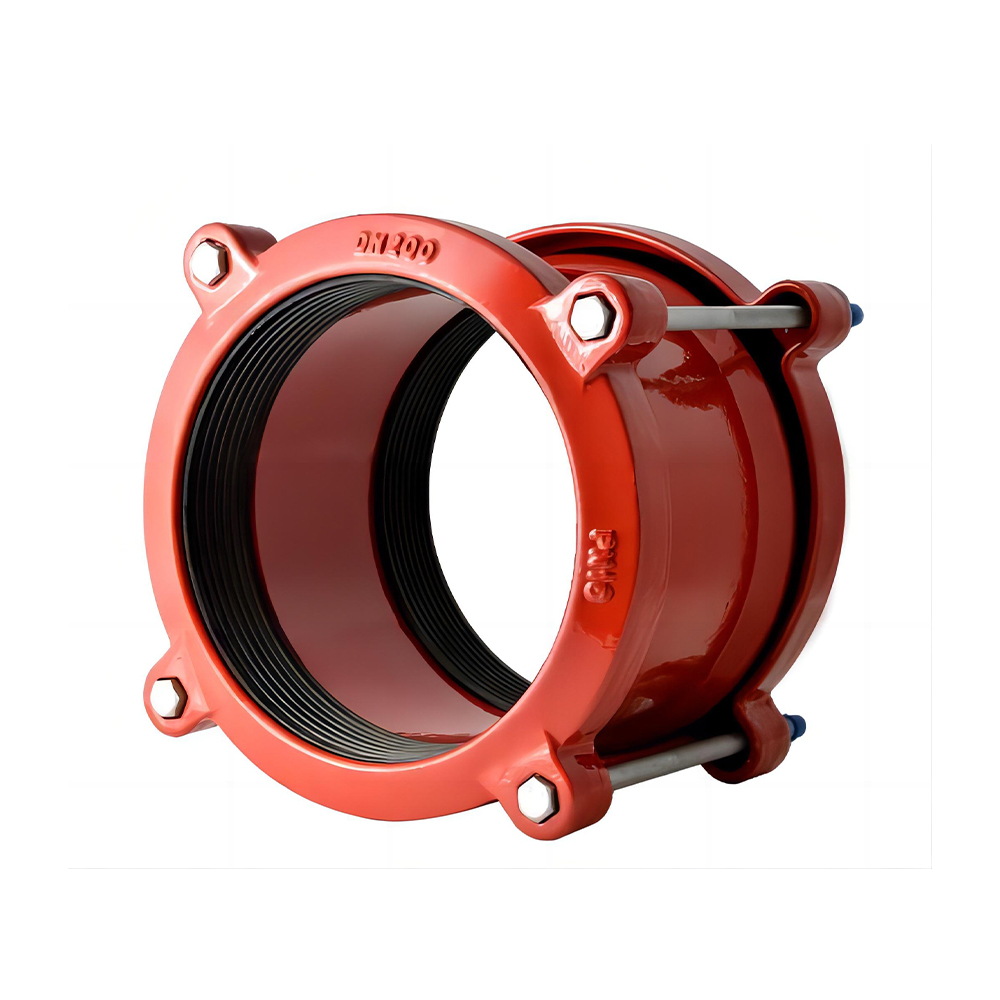
Available configurations
Representative pipe coupling models
These photographs come from the current Conflex product catalogue. Dimensions and availability are confirmed against each enquiry.
Universal Coupling
Wide-range connection for compatible plain-ended water pipes.
View product details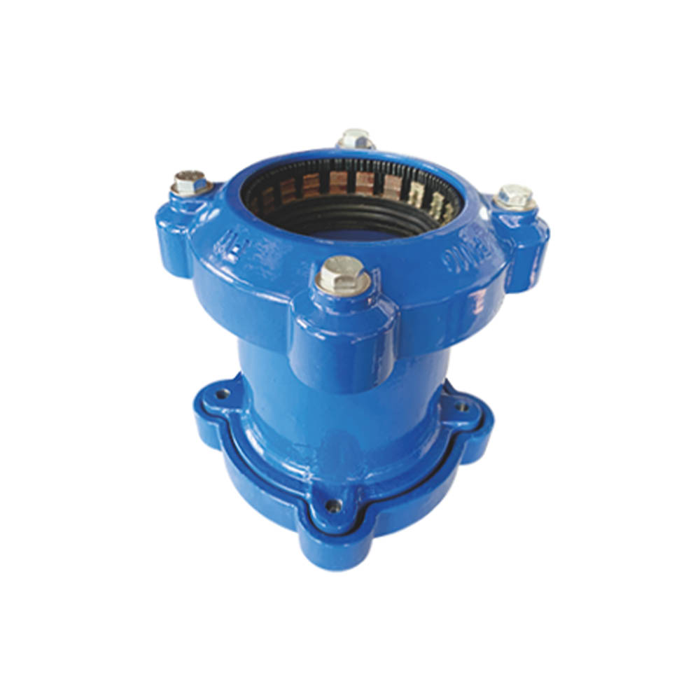
Restrained Universal Coupling
Mechanical gripping configuration for compatible restrained connections.
View product details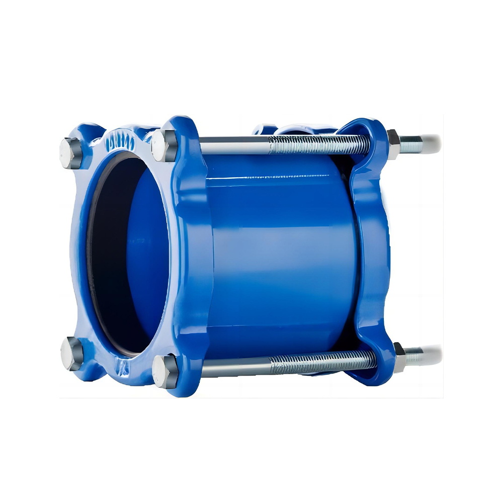
Coupling for DI Pipe
Pipe-specific coupling documented for ductile iron systems.
View product details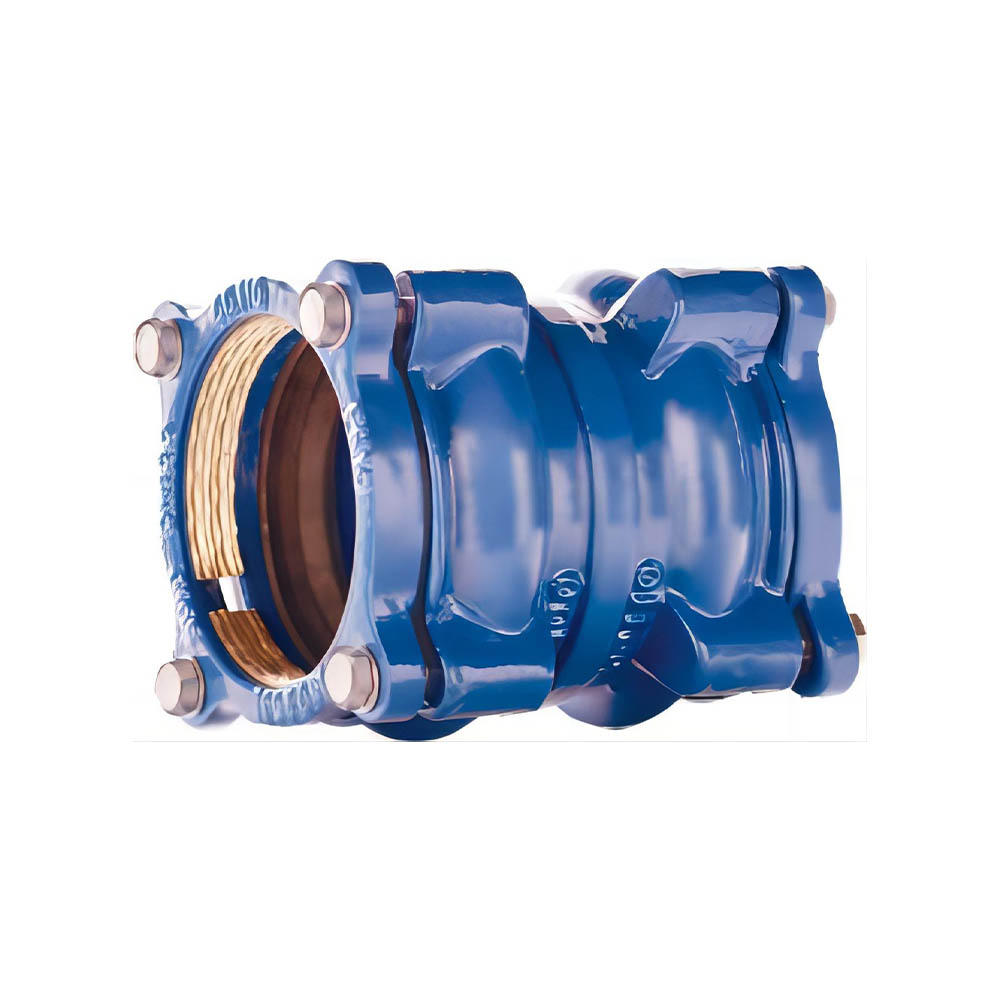
Restrained Coupling for PE Pipe
PE configuration requiring pipe support and project restraint review.
View product detailsTechnical reference
Typical documented range
Values below summarize referenced catalogue models, not a blanket rating for every configuration. The approved drawing and quotation govern the supplied product.
- Reference size coverage
- DN50–DN400 universal; documented pipe-specific ranges extend higher
- Reference pressure classes
- PN10 and PN16 on the documented universal coupling
- Sleeve options
- Ductile iron GGG50 or steel, depending on the selected coupling
- Gasket options
- EPDM, SBR or NBR selected for the service medium
- Reference angular allowance
- Up to ±6° total on the documented Universal Coupling
- Reference temperature
- -10°C to +70°C on documented universal configurations
Typical applications
- New pipeline sections
- Pipe replacement
- Material transitions
- Network rehabilitation
Pipe and connection context
- Ductile iron pipe
- Steel pipe
- PVC pipe
- Selected PE applications
Compatibility depends on the selected model, exact OD, pipe condition and confirmed operating duty.
Installation summary
Five checks before commissioning
This summary does not replace the approved model drawing, torque table, project method statement or safety procedure.
Read the installation guide- 1Verify both pipe outside diameters, coupling range, pressure class and all supplied components.
- 2Clean each pipe end for at least half the coupling length and mark equal insertion reference lines.
- 3Place the glands and gaskets on the pipe ends with the gasket tapers oriented toward the coupling sleeve.
- 4Align the pipe axes, maintain the specified gap and centre the sleeve across the joint.
- 5Move the gaskets and glands into position, then tighten bolts evenly in an alternating sequence and pressure-test.
RFQ checklist
Send these six inputs
If a value is unknown, send a drawing or site photo and mark it for review.
- 1Both pipe materials and outside diameters
- 2Working pressure
- 3Required restraint
- 4Allowable angular deflection
- 5Service medium and temperature
- 6Buried or above-ground condition
Frequently asked questions
Pipe Couplings FAQ
Can a universal coupling join pipes with different outside diameters?
Selected couplings can connect compatible ODs within their stated range. Provide both actual outside diameters so the correct band can be checked.
What is a restrained pipe coupling?
It combines sealing with a mechanical grip intended to control axial movement on compatible pipe materials.
Can universal couplings be used on PE pipe?
Selected configurations are intended for PE applications, but insert support, restraint and pipe SDR requirements must be reviewed for the project.
How much gap should be left between pipe ends?
The documented installation guidance references a 5–10 mm gap for selected products, but the approved drawing and project specification govern.
Need a dimensional table or model review?
Include the size range, standard, quantity and destination in your enquiry.
Ready for technical review?